Hey, it’s spring 2024 and the laser work marches slowly on. Up until this point the most promising design has been an asymmetrical confocal cavity where the beam waist on the gain side of the cavity is larger than the KTP side, with a strong constriction in the region of the Q-switch:

Cavity beam radius in x and y directions, 1000cm thermal lensing.
It turns out this design causes problems as the cavity encounters thermal lensing. As it lenses, the cavity shape changes quite a bit. Here is a plot of the beam radii for a range of thermal lensing. It is far from constant:

Beam diameter for different valuers of thermal lensing.
The changing cavity dynamics shouldn’t matter that much as long as the cavity is perfectly aligned. But after a lot of tweaking, “perfect” alignment is a fantasy. The result is that at certain power levels the laser mode hops to a higher mode, and this kills the performance of green conversion.
The Dual Confocal Resonator
If you balance the confocal part of the resonator to use the same mirror radii on both sides the cavity doesn’t change nearly as much. A problem with this is the KTP side of the resonator has the same beam radius as the gain side, which reduces intensity on the KTP crystal. This reduces the green conversion efficiency. A solution to this is a second confocal region in the cavity that focuses the beam into the KTP:

Dual confocal cavity.
This cavity changes much less in response to thermal lensing;

Beam Radius in response to thermal lensing.
There are some big challenges with this dual confocal design:
I cannot find mirrors for the second confocal part. They need to be specially coated and custom made.
If the beam coming into the KTP is not a parallel, straight beam the KTP will suffer a degree of “phase mismatch” which can hurt its conversion efficiency.
At the bottom of the beam radius graph all the elements of the cavity are listed. This is very complex. In fact, it needs a larger breadboard. To make it fit in my existing chassis I would need to custom make a breadboard of the right size. Not to mention this is going to be a challenge to align.
Laser mirrors are expensive. What does it cost to have custom mirrors made? About 10x what it costs for standard mirrors. Before I bit off that expense I really wanted proof this design would do what I want. I did manage to find a set of mirrors on eBay that should prove the concept. They’re too tight a curvature (100mm vs 150mm) and are only 7mm in diameter so they will be pretty hard to work with. But…they’re $20 each.
I bought them and built the above cavity, changing dimensions where needed to account for the 100mm mirrors. Alignment was pretty tricky — both these mirrors are at an angle so to get the beam to run down the center of the KTP the mirrors need to be offset. My normal larger mirrors are big enough I don’t need to offset them, but these smaller ones need to be shifted or the beam won’t hit them.
Amazingly, I got the cavity to lase without spending too much time on it.
Did it work? Nope. Do you notice that dip on the right side of the cavity? That’s where the KTP is. In my design the KTP is right in the middle where the slope is flattest. That’s important, because the angle of the beam into the KTP can cause phase mismatch and then the conversion suffers. With 100mm mirrors, the dip is much steeper. I hadn’t accounted for this in my simulation and it predicted a pretty good power output. Then I went back and included support for this “focusing divergence” in the model. This graph shows both ignoring and including that divergence.

Difference in output that occurs when there is a steeply angled focal point into the KTP.
Note that even when ignoring the focusing divergence there is a point where conversion drops to zero and recovers. This is caused by too much intensity into the KTP and destructive interference when forming the beam. It doesn’t occur with the 150mm mirrors as they don’t focus as tightly.
One thing the poor conversion in the KTP did get me is a small crater in my KTP crystal:

Laser induced crater in KTP crystal. Crystal width is 3mm.
To give you an idea of how much power circulates a cavity if there is no escape hatch, the damage threshold for this crystal is 500MW/cm^2.
This still might be the best bet. Simulations of a dual confocal design with 200mm mirrors for the first region and 150mm mirrors for the second show 21.4 watts of green output and 43.85% overall optical efficiency. But since this involves nearly $5000 in expense (custom mirrors and a custom breadboard), I’m keeping that design in my back pocket until I completely run out of ideas.
Symmetrical Confocal Resonator
So what if I designed a resonator with a single confocal region that used symmetrical mirrors? Then KTP intensity wouldn’t be high enough for a good conversion rate. Unless. Unless I changed the Q-switch to fire less often and therefore increase the peak pulse power. I’ve been sticking to saturable absorbers with a 80-90% initial transmission, but if I drop this to 70% I can greatly increase the peak output. This increases intensity in the KTP and improves efficiency. Unfortunately it makes laser threshold much higher.
By using 150mm radius mirrors and a 70% Cr:YAG, I predict 14.1 watts of average output at 32.7% efficiency. That’s pretty good for just the cost of a new Cr:YAG crystal. The downside is the lowest power the laser can produce is about 1W at 35A of drive current. Compare that to 900mW @ 20A for the dual confocal design. Neither one is particularly good at delivering lower powers, but that’s 15 additional amps for about the same power.
New Gain Crystal
The last update is to the gain crystal. So far I’ve been using Nd:YVO4 crystals. These are much more efficient than Nd:YAG and don’t require as precise a pump wavelength. However, they have terrible thermal conductivity and this causes a lot of thermal lensing. The numbers I listed above — the 21 watts or 14 watts of output — are not using Nd:YVO4. Instead, these are modeled using Nd:GdVO4. This is a newer gain medium that is similar in performance to Nd:YVO4, but has much better thermal conductivity.
I couldn’t find Nd:GdVO4 crystals on the internet anywhere, at least as “off the shelf” components. I ended up having two crystals custom made by CASIX. Before I ordered them I used MATLAB to compute resonator efficiency as a 3D plot against doping concentration and length, taking thermal lensing into account:
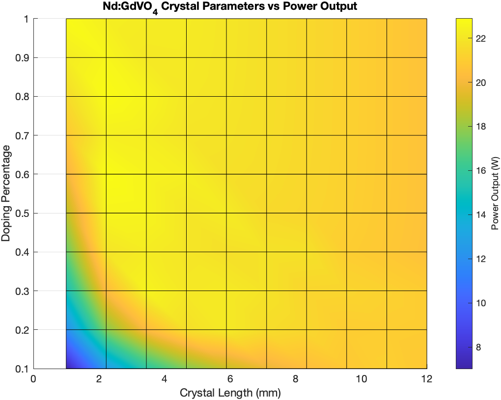
Crystal evaluation in MATLAB.
The crystals I ordered were 8mm long, doped to .5% Nd. While I have been able to get these crystals to lase, the output power tends to be less than for Nd:YVO4. I can’t really crank them up with my bench power supply but in my tests so far they seem to work a little worse.
Results
Well, I built this resonator and ran it through some tests. I had to use a Cr:YAG with T0 = 90% because I have damaged the 80% crystal at some point. It wasn’t working very well so I looked at it under a microscope and it is deeply pitted right where the beam hits. I also didn’t have very good luck running Nd:GdVO4. I couldn't get it to run past a couple hundred mw. This may be due to less thermal lensing, since that is the only thing that is increasing the intensity on the KTP.
However, the Nd:YVO4 and 90% Cr:YAG led to some interesting results because of how I aligned the cavity. Almost all of my laser resonators so far can output a strong peak power and then the actual steady state power drops off. The higher the drive current the faster the power drops off. I had thought this was due to thermal lensing, but I know how to calculate the time it takes for thermal lens to form, and that is on the order of 10’s of ms. So this is something else.
The normal way I align the cavity is to align it with an alignment laser, and then get it running and tweak the alignment at low power to get the best and brightest beam. I did the same this time and took power measurements. Then I tried something new: I cranked the drive current to 30A and then I tweaked the resonator for maximum power.
What I got was quite interesting. I get a laser whose power is very unstable when started but after a few seconds of running stabilizes at a pretty efficient power level that is above what I predict.
This graph shows how the power stabilizes after about fifteen seconds of instability:
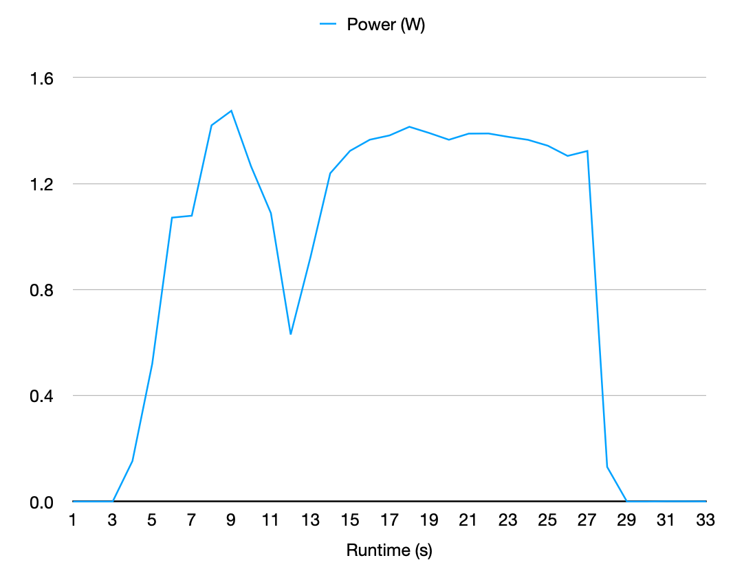
Measured power output with 25A drive current on one pump diode.
This graph shows predicted power output and measured outputs using both “hot” and “cold” alignment techniques:
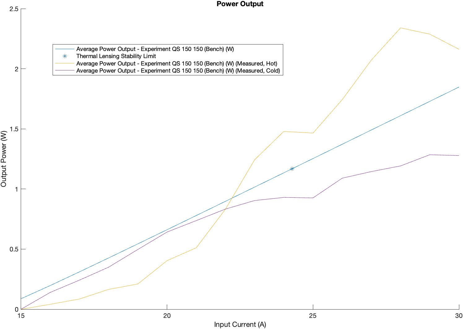
Power output of single confocal cavity.
There are some interesting things to note on this graph:
For the cold case, the measured power starts to diverge from prediction close to where the thermal stability limit is calculated.
For the hot case, this is also about where the power starts to improve above the prediction.
Below the thermal stability limit the “hot” case performs much worse than prediction. Maybe this is because there is not enough thermal load to stabilize the cavity for this “hot” alignment - the cavity is not optimally aligned any more and can’t deliver it's full power.
I think the summary of this experiment is the single confocal cavity can work, but I don’t particularly like having to drive it so hard with a 70% Cr:YAG. Before I took the crater out of the 80% Cr:YAG I do recall having to drive it pretty hard for it to work. The blue line above represents an overall efficiency of 12.5%, which is pretty poor using the 90% crystal.
Next Steps
I had an idea that instead of a second focal point in the resonator I could create a telescope using mirrors to shrink the beam. This would help maintain a parallel beam. Then, after a bit of optics modeling, I realized that that’s exactly what I have been doing when I create a confocal resonator with mismatched curvatures. The sweet spot for those mirrors is a 2:1 compression of the gain to KTP beam size. However, this has always resulted in a cavity that behaves really poorly when it comes to thermal lensing. I can get around that a bit with larger curve radii, so that’s what I’m going to try next. It’s a single confocal resonator with 400mm and 200mm mirrors. This yields really good numbers for Cr:YAG and KTP beam compression, and OK thermal lensing numbers. I’ll refer to these asymmetric cavities as “confocal telescope” cavities, since they combine both a confocal resonator and a beam telescope.
I need new mirrors to try this….and they’re coming Tuesday.