
Now that I have proof I can make the laser work, it’s time to tackle getting the Z-Fold cavity to lase. A Z-Fold cavity allows the laser crystal to be pumped from both ends, which should allow for higher powers and less thermal lensing. But first, I’ve got some maintenance to do on the crystal and mount.
New Mount, New Crystal
The laser crystal I had been using fractured. I’m still not positive why. It is likely one of these two things:
Self Focusing
Thermal Expansion
When a laser is focused into a laser crystal there’s quite a lot of energy put into a very small area of the crystal. Not all of this energy produces useful photons for the laser action. A good portion ends up as heat, and since Nd:YVO4 has very poor thermal conductivity the center of the crystal is much hotter than the outside. This forms a “thermal lens”: the center of the crystal has a different refractive index from the edges, and it physically bulges a little too. Self Focusing happens when the focal point of this thermal lens is inside the crystal itself, and this can be catastrophic. You need a lot of thermal lensing for this to happen with just the crystal, but if you have other curved optics in the resonator (which I do) it is more likely,
Another possibility is the crystal heated up and expanded a little, and my crystal mount was rigid and caused a fracture.
Regardless of the cause, I needed a new crystal. The crystal I cracked was new, 4x4x8 mm and .5% Nd doping. For the kind of pump power I’m using .5% is a little much. eBay has quite a few used crystals and I found one that was originally in a Coherent Avia laser. It’s 3x5x10 mm and .27% Nd. And most importantly the mount Coherent uses has the crystal glued in with thermal silicone. This made it easy to get the crystal out without damaging it.
I also needed a new crystal mount. The one I had may have contributed to the last crystal fracture. I found the pump light was also often hitting the edge of the mount because the crystal wasn’t raised high enough. The mount was too wide and required a lot of space between the crystal and the fold mirrors, and this limited how tightly I could focus the pump beam. The new mount raises the crystal to give clearance for the pump beam and adds mounting holes on the sides to directly mount the fold mirrors.
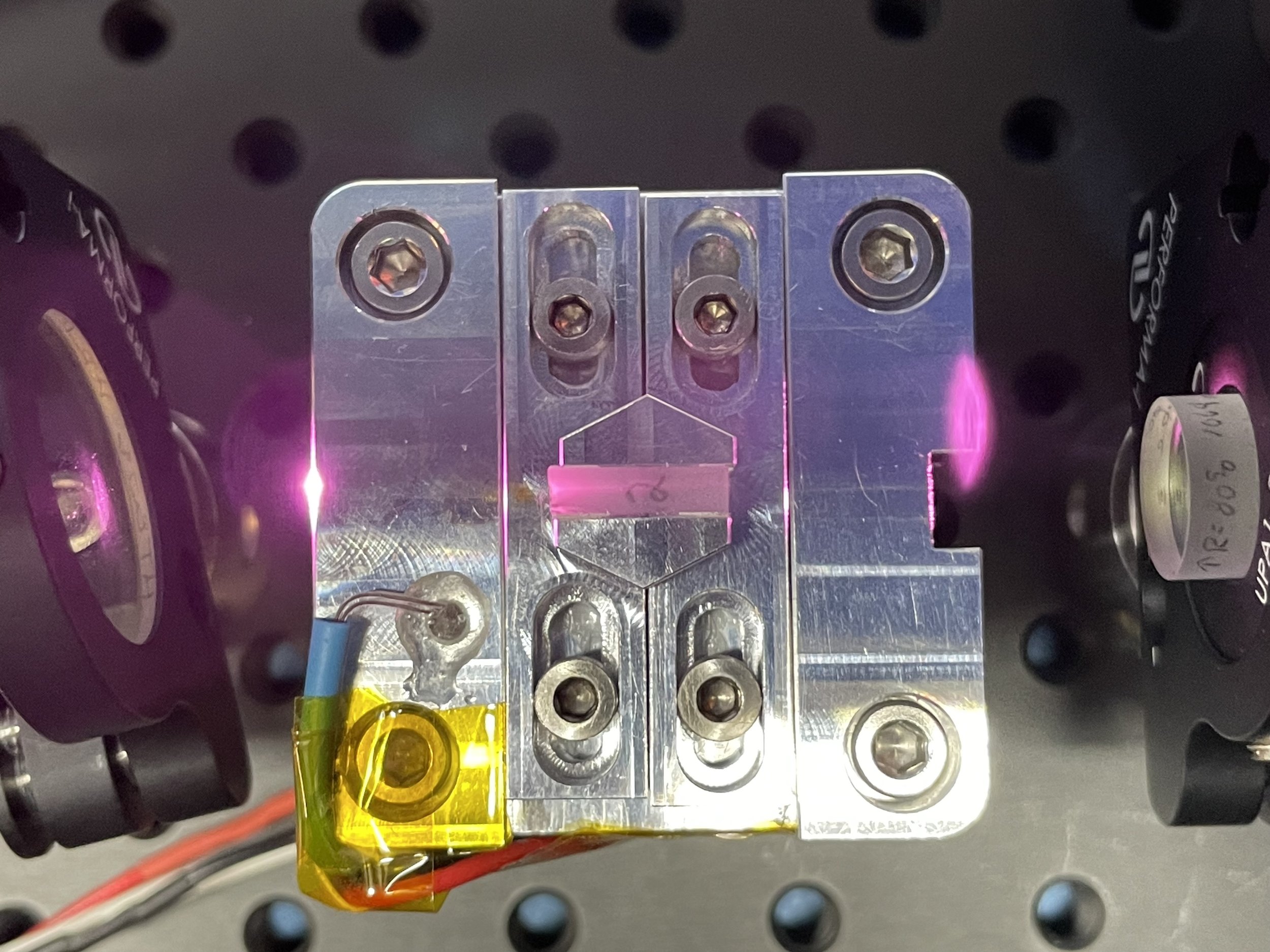
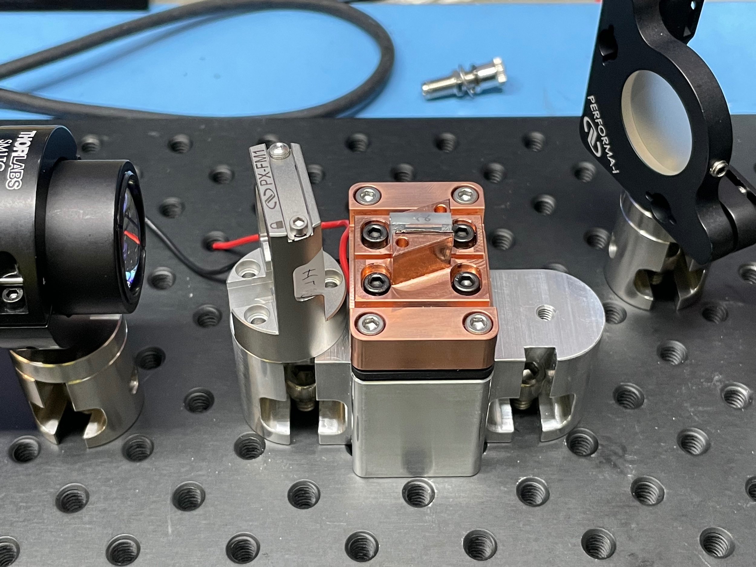
The new mount isn’t perfect either — I wanted to make sure I could get a tight focus into the crystal so I designed the side fold mirror mounts to use a very specific mirror holder. This is a great mirror mount, but has no adjustments and is not a great fit for mirrors inside the resonator that require precise alignment. I got it to work, but I spent a lot of time fiddling with the mirror positions. Had I extended the screw holes by just a few mm I could fit standard adjustable mirror mounts.
Alignment
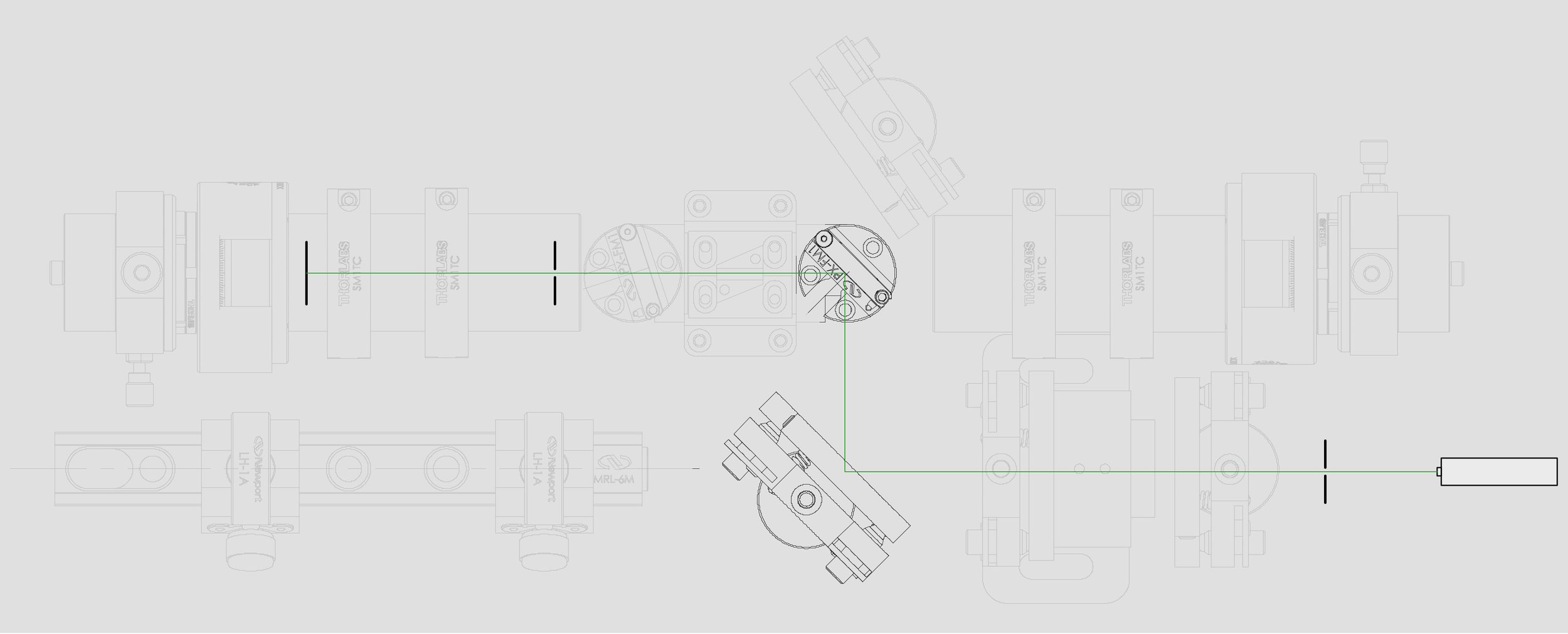
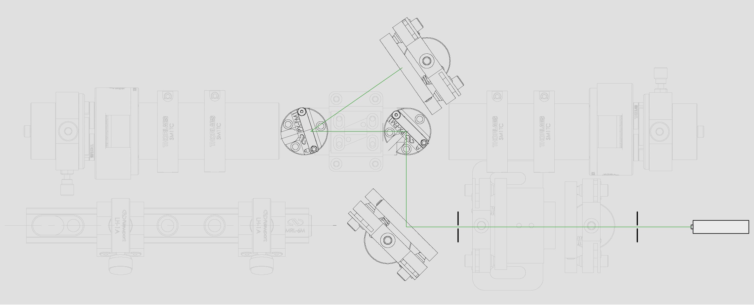
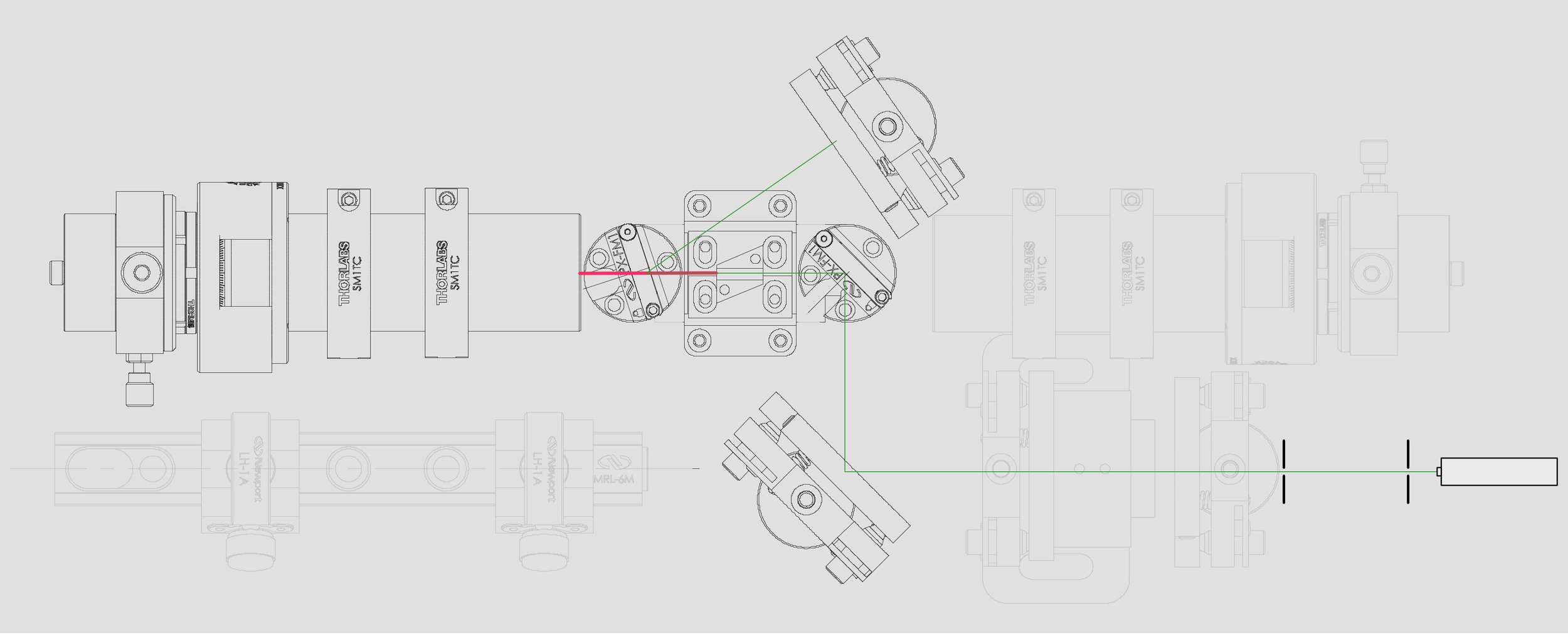
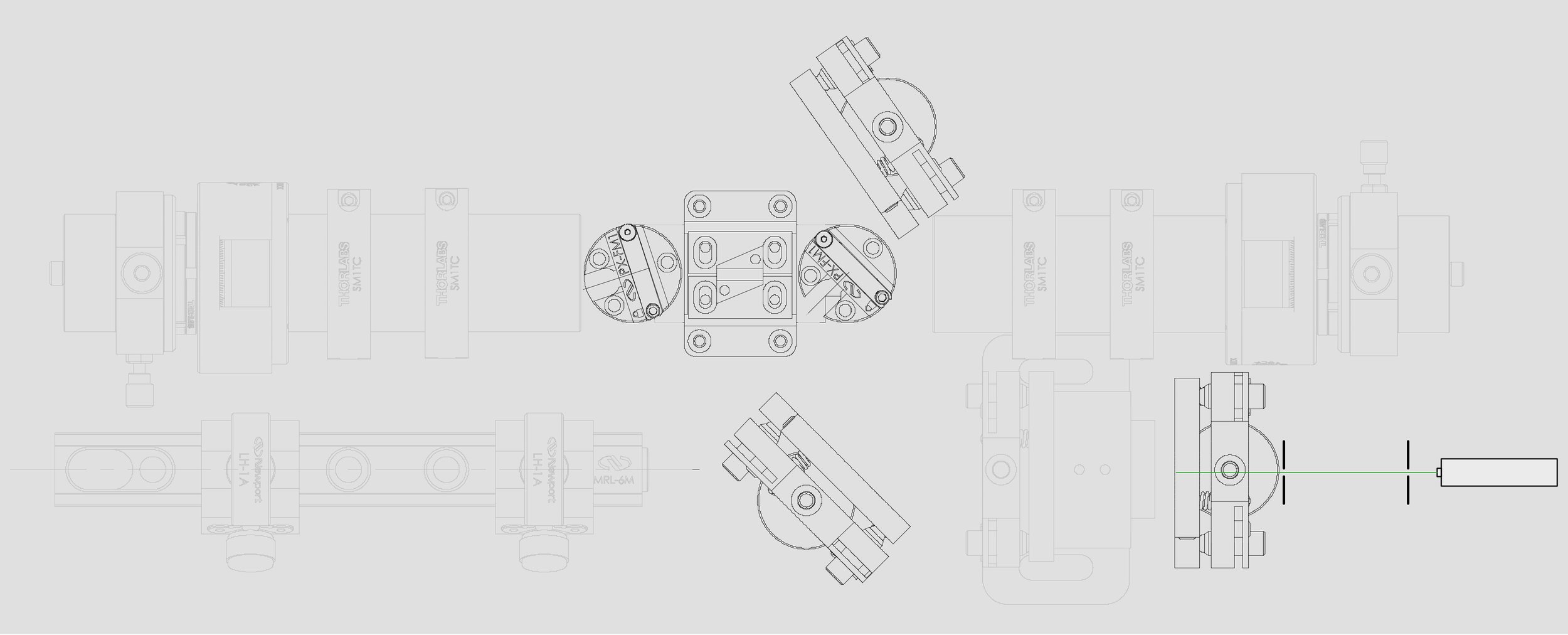
I struggled a lot to get the different cavities aligned. I spent a lot of time thinking about how best to align the Z-fold design. The tricky part is the beam has to be perfect down the center of the laser crystal or else you won’t be able get both pump beams focused on it. Another tricky part is when you add more mirrors it becomes harder and harder to see the reflections. Laser mirrors are designed for specific wavelengths of light and my alignment laser is not one of them. Therefore, the reflection I get off each mirror is only about 4% (Fresnel reflection off glass). After five mirror hops the alignment laser is only .00001% as bright. I dealt with this by:
Using a 532nm 20mw green laser for alignment. This is really too bright to be eye safe so I had pinholes that would fluoresce when hit with the beam, and I could see the glow when wearing laser goggles. Once the beam got back around to where I needed to see the very dim version it was no longer too bright to look at.
I did this in the dark.
I swapped out one of the mirrors in the middle for HR 1064 HR 532, which gives a little more light.
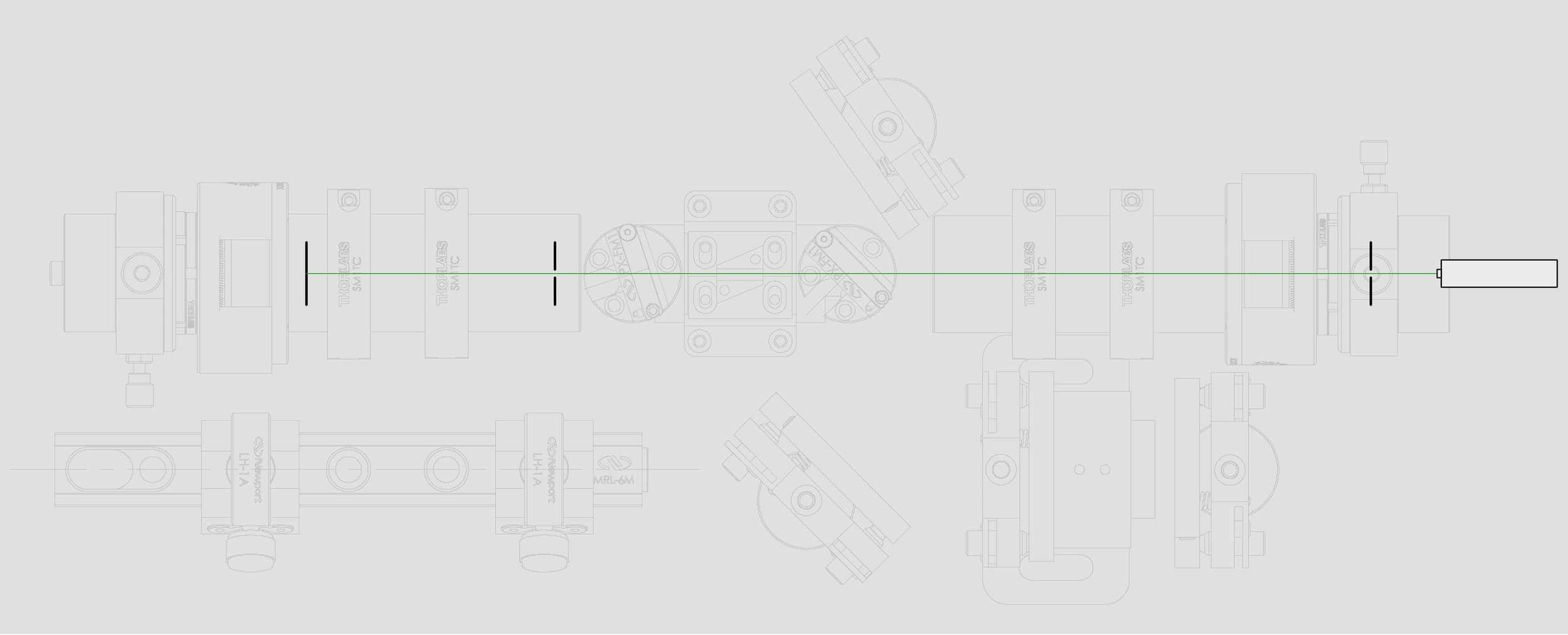
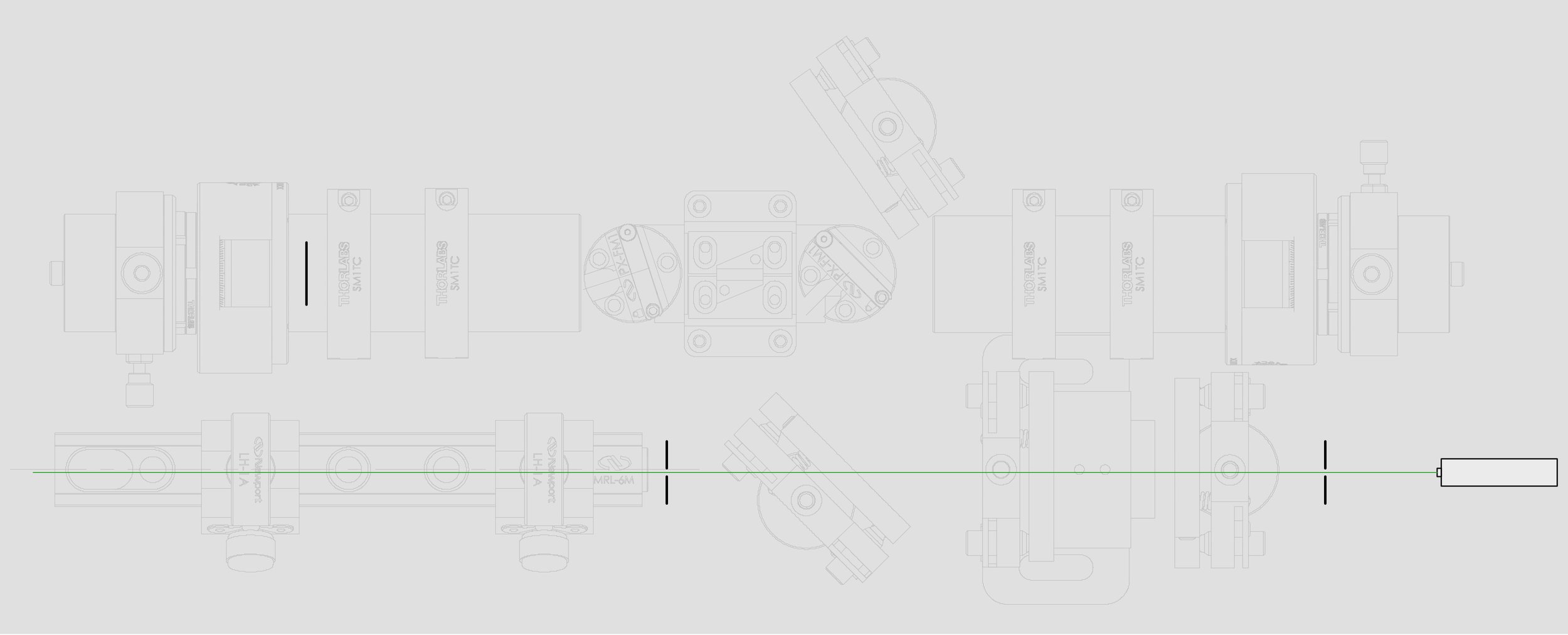
With this, I wrote out a carefully choreographed technique for aligning all five mirrors. In the next set of images I show a CAD drawing of the full Z-fold resonator along with the steps I used to get it aligned. It looks pretty easy to follow. It took me seven hours the first time I did it.


After following these steps I started the left pump and walked the X axis of HR1 until I got laser output. I did this in the dark against an IR target as the initial lasing can be very faint if the mirrors are a little off.
Once the left pump was lasing correctly I did the same with the right pump. No mirror adjustments here — just positioning the right pump so it overlaps the cavity mode volume. Once aligned I started both pumps to make sure the two pumps together weren’t causing any mode hopping.
Conversion to Green
At this point I had a working infrared laser that easily outputs several watts of power. Conversion to green involves three things:
Replacing the HR 1064 / 532 mirror at the OC position with HR 1064 HT 532.
Inserting the KTP crystal and finding the optimal angle for it.
Replacing the 80% output coupler in the HR2 position with a HR 1064 HR 532 mirror.
Step one is the most dangerous. This mirror is on a mount that absolutely should not be adjusted once set and replacing a mirror will cause alignment to suffer. I replaced the mirror and then re-aligned everything.
By leaving the 80% mirror in the HR2 position the green can be maximized safely — there is always some laser output. Green output suffers horribly, but you can still measure it and maximize for it.
When optimized, you get a nice green garage:

Performance
The performance of the laser is, unfortunately, not great. I should be able to get the same amount of green output that I get for infrared. Green conversion is not perfectly efficient, but by putting the KTP crystal inside the resonator I only need about 7% conversion to get the same output I was getting in pure infrared (the optimal output coupler for this setup is 7% transparent). I should be getting about 10 watts of green. I’m only getting about 1 watt. I was able to measure IR leakage through the OC mirror and used this to calculate that the green conversion rate is about 2.2%. This also causes the intracavity power to be pretty high — about 42 watts. But it is below the damage thresholds for my optics.
Why? Well, I don’t know. I have a lot of ideas, and I know there are losses in places. But testing out each idea at this point is expensive. For example, the beam waist inside the KTP could be too big. But it’s about a thousand dollars in new mirrors to change that.
I had assumed the energy density inside the cavity would automatically balance — the intracavity density would continue to rise until the harmonic conversion reached the optimal output percentage. But it doesn’t. I think what happens is it does balance, but it doesn’t balance to the optimal output coupling percentage. It balances to the lowest output coupling needed to prevent the intracavity power density from climbing higher for the given pump power. I could get higher powers here, but I am stopped by thermal lensing because the intracavity density is too high and causing more thermal lensing.
I’m going to continue the project and finish building a case for it. There’s only so long I can leave these optics in my garage before they become dirty. Once I have the case done I plan to learn a lot more physics and start digging into the poor performance.