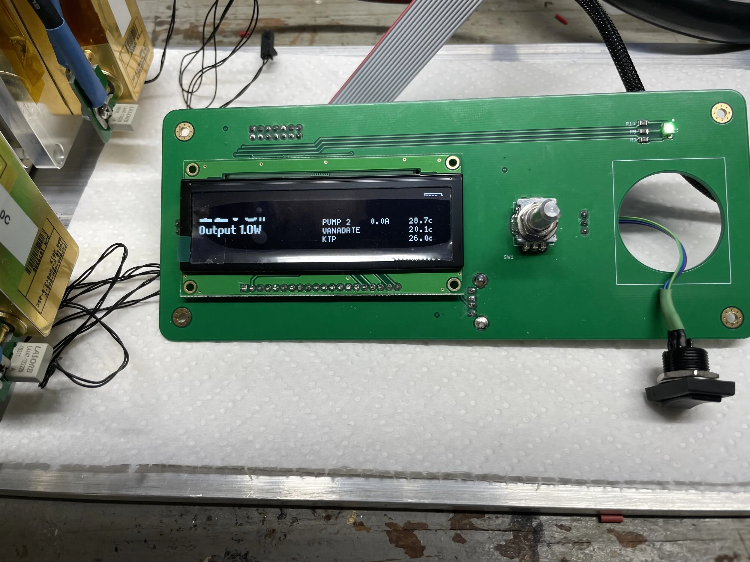
I’ve finished the control board for The Laser Project. This is a small AVR-based microcontroller board with a simple OLED screen and a rotary encoder for making selections. There are some shots of it working below.
Outgrowing an AVR?
When I started this project two years ago I intended to use AVR microcontrollers. They’re simple, easy to program, and have a ton of support through the Arduino libraries (and yes, I unabashedly use Arduino libraries because writing a whole display controller isn’t something I want to spend my time on).
I’m using the largest AVR I can get and I spent many many days cutting the software down so it would fit in memory. While debugging it, I had to remove sections of code just to be able to add debug logic. But I got it all to fit. There’s not a ton of features: on the UI side you can control the drive current, and there is EEPROM based configuration for maximum diode currents, TEC temperatures, etc. The bulk of the code is in the power and TEC board drivers. There is also a serial interface where you can query for lower level status with dedicated USB to serial hardware.
The control board also has a bunch of logic around displaying charge status when charging the battery and safety interlocks around temperature, current, etc. I don’t want any software or hardware problems to fault the laser on. It also soft starts the laser drivers to help keep them happy.
Bodge Wires
If you look at the component side of the board you’ll see a lot of bodge wires. This is the first revision of the board, and due to the component shortage parts on this board are back ordered until July 2023, so I was pretty motivated to make it work. Things I messed up:
There is no pull-up on the chip select line for the display, so when programming the display goes crazy and messes up the SPI signal enough that programming fails.
Ug. Serial lines. I messed up that the read line goes to the write line and vice versa due to the dumb way serial data flow is defined. I only messed this up on the programming header, but hey, I need that interface on the programming header.
I am using a hardware debounce chip to debounce all the buttons. This doesn’t work on the rotary encoder because the debounce time (100ms typical) is so long all but the slowest rotations are reported. This was kind of tricky to fix because all buttons go to a dedicated GPIO chip and I’m using interrupts to drive changes. This design is kind of a pain to debounce and I created a pending input section that can throw away data if it finds it bounced. It’s not perfect, but works well enough.
Repeat after me: do not use an external GPIO expander to provide a chip select line for another peripheral on the same bus. There’s no way to deselect when you’re done.
New Chips
There are a couple new chips on this board I’ve never used before that I wanted to call out.
MAX6818 - This is a hardware debounce chip and while it did fail for my rotary encoder it’s fantastic for all the other switches. It provides its own pull-ups and aside from a bypass capacitor needs no other parts. It implements a shift-register based counter for calculating debounce and makes the software part completely trivial. It can do eight switches, ,so this is much smaller than any other hardware option I’ve seen.
XRA1402 - An eight port IO expander. I really filled up the AVR’s IO ports and needed a few more ports. I love this thing. It’s super configurable, especially its interrupt line. You can configure each pin for rising or falling edges. This was great for the encoder because I could just configure for the right edge pattern and figuring out encoder turn direction became three lines of code.
Final Thoughts
I’ve been running things off a wire-snarl of a bread board for a long time. This control board makes things significantly easier. This is the last circuit board I need for The Laser Project. Now it’s all physics. This blog is a little behind, though, because there has already been a great deal of physics in the garage. Some successes….and some rather expensive failures. That’s next.


